This document shows a method of allowing the use of DHCP servers (such as Windows or Linux) that are on your network to service DHCP for network attached devices. This is an alternative to using the built in DHCP from Omada.
Assumptions
- Multiple VLANs
- Multiple Omada Switches
- Omada Router
- Omada AP (not talked about in this)
- Omada Controller, Software or Hardware based
- Omada 5.13.24
- All Omada hardware will have its management IP on VLAN 1
- DHCP and DNS set up on servers. In this case, Windows 2016 Domain Controllers
- 192.168.30.131
- 192.168.30.132
VLANs
| 1 | VLAN1-MGMT | 192.168.0.0/24 |
| 10 | VLAN10-Office | 192.168.10.0/24 |
| 20 | VLAN20-Media | 192.168.20.0/24 |
| 30 | VLAN30-Servers | 192.168.30.0/24 |
| 50 | VLAN50-Wifi | 192.168.50.0/24 |
- Set up VLANs in Omada
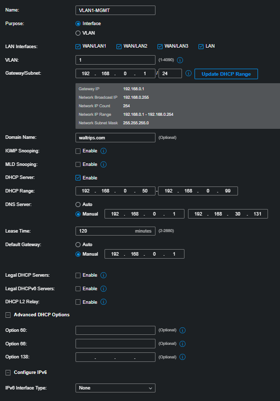
- Configure VLAN1_MGMT
| Name | VLAN1_MGMT (Management) |
| Purpose | Interface |
| LAN Interfaces | Select All of them |
| VLAN | 1 |
| Domain Name | yourdomain.com |
| Gateway/Subnet | 192.168.0.1/24 |
| IGMP Snooping | Unchecked |
| DHCP Server | Checked |
| DHCP Range | 192.168.0.50 – 192.168.0.99 |
| DNS Server | Manual – 192.168.30.131, 192.168.30.132 |
| Lease time | 120 |
| Default Gateway | Manual – 192.168.0.1 |
| DHCP Omada Controller | Blank |
| Legal DHCP Servers | Unchecked |
| Legal DHCPv6 Servers | Unchecked |
| DHCP L2 Relay | Unchecked |
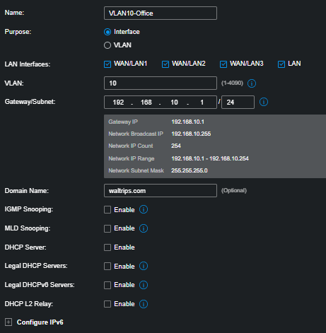
- Do the same for the other VLANs.
| Name | VLAN10-Office |
| Purpose | Interface |
| LAN Interfaces | Select All of them |
| VLAN | 10 |
| Domain Name | Yourdomain.com |
| Gateway/Subnet | 192.168.10.1/24 |
| IGMP Snooping | Unchecked |
| DHCP Server | Unchecked |
| Legal DHCP Server | Unchecked |
| Legal DHCPv6 Servers | Unchecked |
| DHCP L2 Relay | Unchecked |
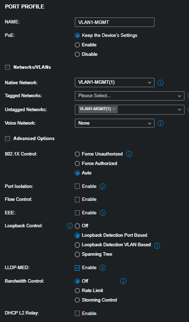
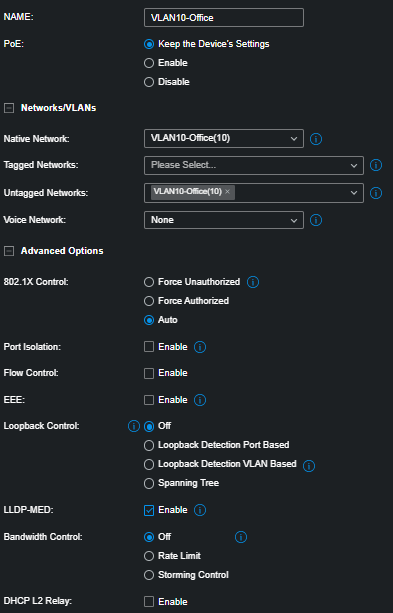
- Profiles are created automatically when VLANs are created
- Update/Verify profile VLAN1-MGMT
- Update/Verify profile VLAN10-Office, and Media and Server
Switch Config
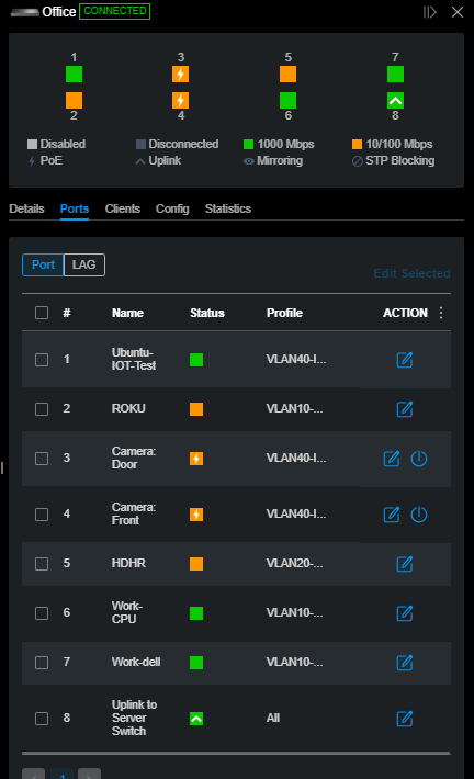
- Select Switch from the Devices page
- Each switch should have an uplink to the router. Choose the same port on each switch.
- Each switch will have a management IP on VLAN 1
- Use the “ALL” profile for the Uplink port.
- Assign the Other VLAN profiles to the rest of the ports as needed to support attached devices
Configure Interfaces
- Select Config–>VLAN Interface
- Turn on all interfaces
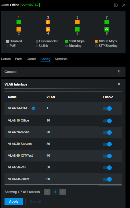
This function is what allows DHCP to flow from your DHCP servers down to the ports on your switches.
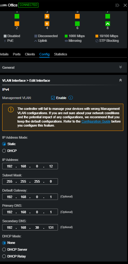
- Select each VLAN Interface and edit it
VLAN1-MGMT – Management Network
| Management VLAN | Checked |
| IP Address Mode | Static |
| IP Address (This will be the IP address assigned to the switch) | 192.168.0.12 |
| Subnet Mask | 255.255.255.0 |
| Default GW | 192.168.0.1 |
| Primary DNS | 192.168.30.131 |
| Secondary DNS | 192.168.30.131 |
| DHCP Mode | None |
| IPV6 | Unchecked |
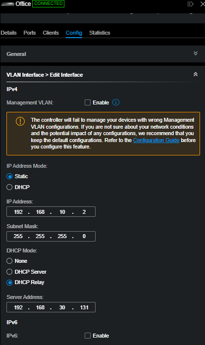
Set up Remaining VLANS
- Note that each VLAN has its own IP
- Note the Last Octet will be different for each Switch
- Office Switch is xx.xx.xx.2
- Media Switch is xx.xx.xx.3
- Server Switch is xx.xx.xx.4
| VLAN10-Office | VLAN20-Media | VLAN30-Servers | |
| Management VLAN | Unchecked | Unchecked | Unchecked |
| IP Address Mode | Static | Static | Static |
| IP Address | 192.168.10.2 | 192.168.20.2 | 192.168.30.2 |
| Subnet Mask | 255.255.255.0 | 255.255.255.0 | 255.255.255.0 |
| DHCP Mode | DHCP Relay | DHCP Relay | DHCP Relay |
| Server Address | 192.168.30.131 | 192.168.30.131 | 192.168.30.131 |
- Note the IP Address. This will be the IP for the appropriate VLAN.
- Note the last octet. This will be the same for each Interface on each switch
- Each VLAN ends up with an IP on the switch for that VLAN.
Here is a sample for 3 switches:
| Switch | VLAN | VLAN Interface IP |
| Office | 1 | 192.168.1.12 – admin IP |
| Office | 10 | 192.168.10.2 |
| Office | 20 | 192.168.20.2 |
| Office | 30 | 192.168.30.2 |
| Media | 1 | 192.168.1.13 – admin IP |
| Media | 10 | 192.168.10.3 |
| Media | 20 | 192.168.20.3 |
| Media | 30 | 192.168.30.3 |
| Servers | 1 | 192.168.1.11 – admin IP |
| Servers | 10 | 192.168.10.4 |
| Servers | 20 | 192.168.20.4 |
| Servers | 30 | 192.168.30.4 |
Once these settings are applied, you should be able to provide DHCP to all VLANs (excepting the manangement VLAN) from a source such as Windows or Linux DHCP servers.
Each switch ends up with a virual interface for each VLAN to route this. (xx.xx.xx.2, 3, 4, etc.)